A007 EPC (schematic)
Overview
Below you will find the schematic for A007 EPC as well as key operational features and additional support information to assist with your installation.
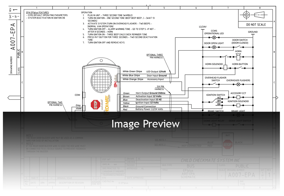
Installation Schematic: A007 EPC
- The emergency door Buzzer circuit can be utilized to transmit the deactivation signal from RVT button to the module. The red wire on the RVT should be connected in this configuration to stop feedback onto the door buzzers.
- If there is no Buzzer circuit please use a direct connection from the RVT blue wire to the EP1plus blue wire
- The brown activation wire is typically connected to the red overhead lights or another 12V source (eg. brakes).
Operation Features
- Activation by the 8-way overhead red lights (or another 12V source)
- Deactivates in Key OFF position
- Front door is monitored and must be closed during deactivation
- 1 minute to perform the child check
- Horn will sound for 5 minutes if the child check is not done
- To silence the alarm, cycle the key off and then back to on
Optional Features
- Dome lights illuminate for 2 minutes after deactivation
- Can wait in Accessory position for up to 4 minutes (can be extended by cycling the key)
Order Information
Module & Instructional Decal: A007 EPC
Component Kit: AC01
- P100: 6-pin wire Harness
- A033: RVT Deactivation Button
Upgraded Component Kit: AC31 (For dome light, accessory and pilot light feature, LED not supplied)
- A033: RVT - Deactivation Button
- P100: 6-Pin Wire Harness
- A026: 3-Pin Diode Wire Harness
- P038: 2-Pin Wire Harness